Serialisation, provisioning and factory test
1. Executive Summary & Production Policy
Mass-manufacturing connected IoT devices needs rigorous automated checks before units leave the contract manufacturer. Each printed circuit board assembly (PCBA) is verified, given a deterministic identity, injected with its keys and locked. Inadequate factory testing results in high return rates and field dead-on-arrivals (DOA), while compromised provisioning processes introduce forged identities and supply chain vulnerabilities.
This standard governs hardware serialization numbering schemes, hardware root-of-trust provisioning, automated test fixtures (ATE / bed-of-nails), RF calibration, and physical debug port locking.

Manufacturing end-of-line testing, provisioning, and locking sequence.
2. Universal Hardware Serialization Scheme
Every manufactured device must possess globally unique, tamper-evident identifiers inscribed in both digital non-volatile memory and physical external housing.
2.1 Identifier Taxonomy
| Identifier Type | Standard / Format | Storage Location | Visibility | Purpose |
|---|---|---|---|---|
| Hardware Serial Number | GS1 AI(21) alphanumeric string (16-32 chars) | Internal OTP Flash / Secure Element | Laser-etched 2D DataMatrix barcode | Inventory tracking, warranty, and field logistics |
| IEEE MAC Address | IEEE EUI-48 / EUI-64 hexadecimal | Secure Element / Radio OTP registers | Network frames | Local wireless addressing (BLE, Wi-Fi, 802.15.4) |
| Cellular Identity (IMEI) | 15-digit decimal string (3GPP TS 23.003) | Cellular Baseband NVRAM | Carrier network registration | Cellular operator whitelisting and SIM pairing |
| Cryptographic Device ID | SHA-256 fingerprint of Device Public Key | Secure Element X.509 Certificate | Cloud authentication handshake | Zero-touch cloud onboarding and mutual TLS (mTLS) |
Standard identifiers assigned during factory provisioning.
2.2 External Laser Marking & Optical Verification
- All outer enclosures and internal PCB shields must be marked with a high-contrast 2D DataMatrix (ISO/IEC 16022) or QR Code containing the serial number and device public key hash.
- The automated test fixture must verify readability using an industrial vision camera before releasing the board clamp.
3. Cryptographic Provisioning & Hardware Root of Trust
Hardcoding shared symmetrical keys or compiling private keys directly into firmware binary images is strictly prohibited. Every connected device must incorporate a dedicated Secure Element (such as Microchip ATECC608, NXP SE050, or Infineon OPTIGA Trust M) or an on-die Hardware Security Module (HSM).
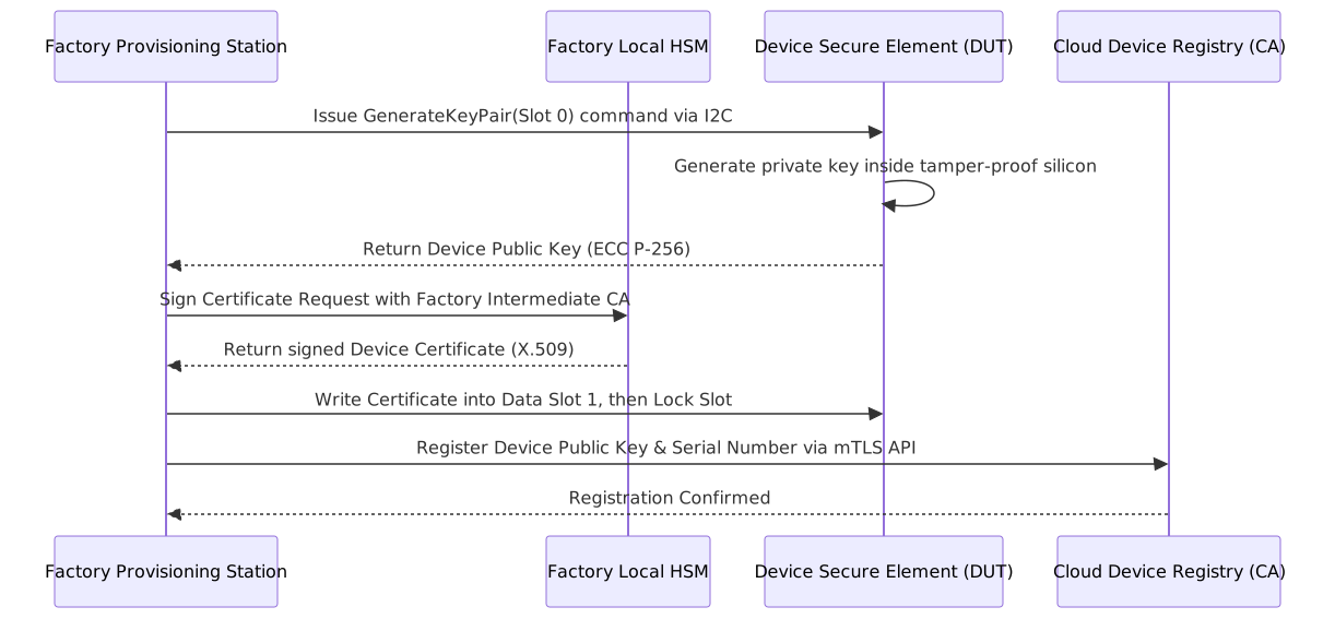
Secure on-die key generation and certificate signing workflow.
3.1 Provisioning Rules
- On-Die Private Key Generation: Private keys must be generated inside the Secure Element itself using a hardware True Random Number Generator (TRNG). Private keys must never leave the silicon boundary under any circumstance.
- Air-Gapped Factory HSM: Device certificates must be signed locally at the contract manufacturer by a hardware security module (HSM) holding a restricted intermediate factory CA certificate. The root CA remains offline.
- Permanent Slot Locking: Once the public certificate, device configuration flags, and I2C address are programmed into the Secure Element, the manufacturing script must blow the configuration fuses (
lock_configandlock_data).
4. Automated Test Equipment (ATE) Fixture Design
To achieve deterministic test throughput (\< 45 seconds per unit), production lines must use custom Bed-of-Nails (Pogo Pin) automated test fixtures:

Bed-of-nails fixture subsystem layout for automated production line testing.
4.1 Mandatory Test Phases
Every production board must pass four sequential test gates:
- Power-On Short-Circuit & Quiescent Check: Before full voltage is applied, the fixture checks for short circuits on all power rails. The power analyzer measures initial quiescent current to confirm it matches nominal baseline (\(\pm 10\%\)).
- Firmware Flashing & Integrity: The production bootloader, primary application image, and factory diagnostic firmware are flashed via high-speed SWD. Readback CRC32/SHA-256 checksums are verified against the master build manifest.
- Conducted RF Verification: To avoid antenna interference from neighboring factory equipment, RF performance is verified through a spring-loaded coaxial switch probe directly contacting the PCB RF test pad. The system verifies transmission power (Tx Power \(\ge +20\,\mathrm{dBm}\)) and receiver sensitivity across operating bands.
- Sensor Calibration: Onboard sensors (accelerometers, temperature sensors, pressure transducers) are calibrated against precision reference standards in the fixture, and offset calibration factors are written to flash.
5. Security Hardening: Debug Interface Locking
Leaving physical debug interfaces (JTAG, SWD, UART bootloaders) enabled on field-deployed products allows adversaries to dump firmware binaries, reverse-engineer proprietary algorithms, and extract cryptographic credentials.
Caution
Every device undergoing end-of-line packaging must have its hardware debug interfaces permanently disabled via One-Time Programmable (OTP) hardware fuses before leaving the manufacturing station.
5.1 Debug Port Disabling Procedure
- After passing all functional tests and certificate verification, the test orchestrator executes the hardware lock command (for example, programming STM32 Readout Protection to RDP Level 2, or blowing NXP / Nordic access port protection fuses - APPROTECT).
- Once RDP Level 2 is active, the SWD/JTAG debug port is permanently disabled at the silicon level. Debug probes can no longer connect, halt execution, or inspect memory.
- The test station verifies that the debug probe can no longer read flash or registers. If the port remains open, the board is rejected.
6. Manufacturing Database Integration & Traceability
- Centralized Manufacturing Execution System (MES): Every test step, voltage measurement, RF power reading, and certificate hash must be logged in real time to the enterprise MES database indexed by the unique hardware serial number.
- Anti-Cloning Rules: The MES must reject duplicate serial numbers or certificate requests immediately.
- Defect Quarantining: Any board failing a test gate must have its serial number blacklisted in the cloud device registry, preventing rejected factory scrap from ever connecting to production cloud environments.