Electronics, embedded and code
Schematics, signals, wiring, chips, memory, logic and code. The first four are drawn by tools in the container; the rest are poster blocks.
circuit
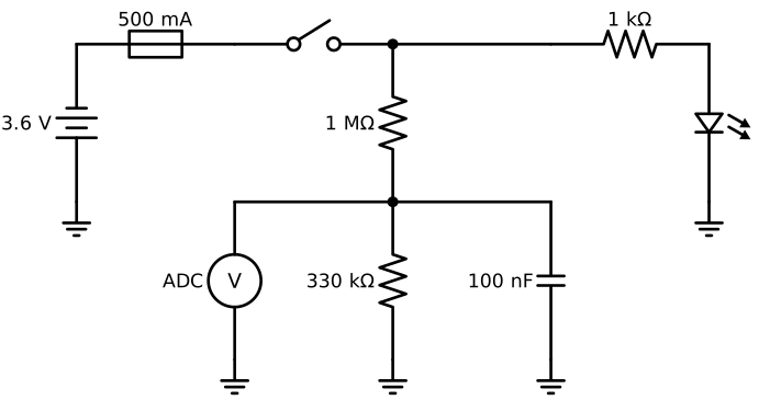
A schematic, one element a line: [name:] element [label] | direction | at name.anchor | to name.anchor. Each element goes on from the end of the one before. Here, the battery voltage through a divider to the analogue-to-digital converter (ADC), with a filter capacitor and a status light-emitting diode (LED).
```circuit
V1: battery 3.6 V | up
F1: fuse 500 mA | right
SW1: switch | right
J1: dot
R1: resistor 1 MΩ | down
J2: dot
R2: resistor 330 kΩ | down
ground
line | at J2.end | right
C1: capacitor 100 nF | down
ground
line | at J2.end | left
ADC: meter-v ADC | down
ground
line | at J1.end | right
R3: resistor 1 kΩ | right
LED1: led | down
ground
ground | at V1.start
```
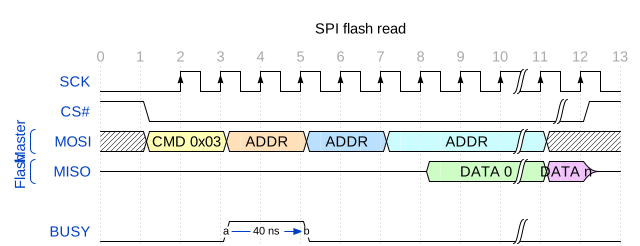
wavedrom
Digital timing: clocks, data with values, groups and arrows between edges.
```wavedrom
{ "signal": [
  { "name": "SCK",  "wave": "0.P.......|..", "period": 1 },
  { "name": "CS#",  "wave": "10.........|1" },
  ["Master",
    { "name": "MOSI", "wave": "x3.4.5.6..|x.", "data": ["CMD 0x03", "ADDR", "ADDR", "ADDR"] }
  ],
  ["Flash",
    { "name": "MISO", "wave": "z.......7.|8z", "data": ["DATA 0", "DATA n"] }
  ],
  {},
  { "name": "BUSY", "wave": "0..1.0....|..", "node": "...a.b" }
],
  "edge": ["a~>b 40 ns"],
  "head": { "text": "SPI flash read", "tick": 0 },
  "config": { "hscale": 1 }
}
```
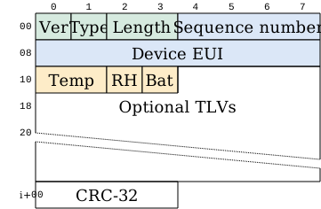
bytefield-svg
The fields of a message or register, byte by byte, in its Clojure-like language.
```bytefield-svg
(defattrs :bg-green {:fill "#d6eadf"})
(defattrs :bg-blue {:fill "#dbe7f7"})
(defattrs :bg-amber {:fill "#fdecc8"})
(def boxes-per-row 8)
(draw-column-headers)
(draw-box "Ver" [:bg-green {:span 1}])
(draw-box "Type" [:bg-green {:span 1}])
(draw-box "Length" [:bg-green {:span 2}])
(draw-box "Sequence number" [:bg-blue {:span 4}])
(draw-box "Device EUI" [:bg-blue {:span 8}])
(draw-box "Temp" [:bg-amber {:span 2}])
(draw-box "RH" [:bg-amber {:span 1}])
(draw-box "Bat" [:bg-amber {:span 1}])
(draw-gap "Optional TLVs")
(draw-box "CRC-32" [{:span 4}])
(draw-bottom)
```
wireviz
A wiring harness in YAML: connectors with their pins, cables with their wire colours, and the connections between them.
```wireviz
connectors:
  J1:
    type: JST PH
    subtype: female
    pinlabels: [VBAT, GND, SDA, SCL]
  J2:
    type: Molex Micro-Fit
    subtype: female
    pinlabels: [GND, VBAT, SCL, SDA, NC, NC]
  BAT:
    type: Cell holder
    pinlabels: [+, "-"]
cables:
  W1:
    wirecount: 4
    gauge: 0.25 mm2
    length: 0.3
    colors: [RD, BK, BU, YE]
    shield: true
  W2:
    wirecount: 2
    gauge: 0.5 mm2
    length: 0.1
    colors: [RD, BK]
connections:
  -
    - J1: [1, 2, 3, 4]
    - W1: [1, 2, 3, 4]
    - J2: [2, 1, 4, 3]
  -
    - BAT: [1, 2]
    - W2: [1, 2]
    - J1: [1, 2]
```

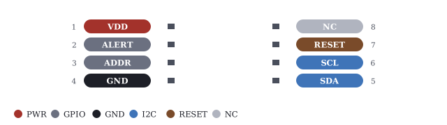
pinout: dual in-line package (DIP)
The pins of a chip with their functions, each function in its own colour with a legend.
```pinout package=dip title="Sensor interface, DIP-8"
1 | VDD | pwr
2 | ALERT | gpio
3 | ADDR | gpio
4 | GND | gnd
5 | SDA | i2c
6 | SCL | i2c
7 | RESET | reset
8 | NC | nc
```
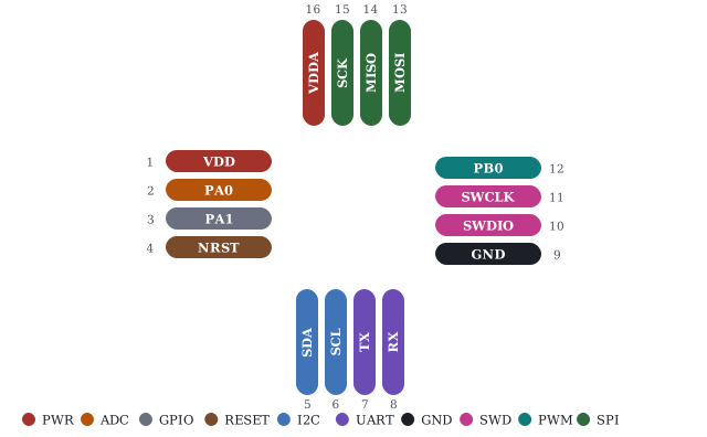
pinout: quad flat no-lead (QFN)
Pins on all four sides of a quad package.
```pinout package=qfn title="SN-100 controller, QFN-16"
1 | VDD | pwr
2 | PA0 | adc
3 | PA1 | gpio
4 | NRST | reset
5 | SDA | i2c
6 | SCL | i2c
7 | TX | uart
8 | RX | uart
9 | GND | gnd
10 | SWDIO | swd
11 | SWCLK | swd
12 | PB0 | pwm
13 | MOSI | spi
14 | MISO | spi
15 | SCK | spi
16 | VDDA | pwr
```
pinout: header
A pin header in rows.
```pinout package=header rows=2 title="Debug and expansion header, 2x6"
1 | 3V3 | pwr
2 | GND | gnd
3 | SWDIO | swd
4 | SWCLK | swd
5 | NRST | reset
6 | TX | uart
7 | RX | uart
8 | GPIO1 | gpio
9 | SDA | i2c
10 | SCL | i2c
11 | ANT_EN | rf
12 | VBAT | pwr
```

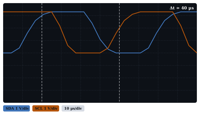
instrument: oscilloscope
Channels in volts on a graticule, with cursors and the time between them.
```instrument type=scope vdiv=1 tdiv="10 µs" cursors=2,6 title="The rise of SDA, 4.7 kΩ pull-up"
SDA | blue | 0 0 0.4 1.6 2.6 3.1 3.3 3.3 3.3 3.3 3.3 2.4 1.1 0.3 0 0 0 0 0.4 1.6 2.6 3.1 3.3 3.3 3.3
SCL | amber | 3.3 3.3 3.3 3.3 3.3 3.3 3.3 2.2 0.6 0 0 0 0 0.4 1.6 2.6 3.1 3.3 3.3 3.3 3.3 3.3 2.2 0.6 0
```
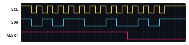
instrument: logic analyser
Digital lines as 0s and 1s.
```instrument type=logic title="I2C read of the sensor"
SCL | 1101010101010101010101010101111
SDA | 1100110011110000110000110011111
ALERT | 1111111111111111111100000000000
```
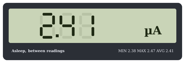
instrument: meter
A multimeter reading, with its minimum, maximum and average.
```instrument type=meter value="2.41 µA" label="Asleep, between readings" min="2.38" max="2.47" avg="2.41"
```
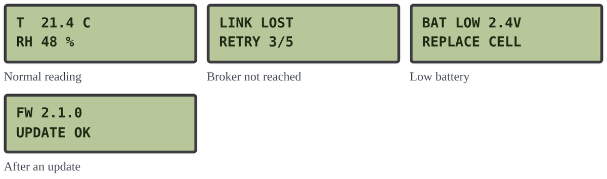
lcd
Screens of a character display, a caption each.
```lcd cols=3
T  21.4 C
RH 48 %
-- Normal reading

LINK LOST
RETRY 3/5
-- Broker not reached

BAT LOW 2.4V
REPLACE CELL
-- Low battery

FW 2.1.0
UPDATE OK
-- After an update
```
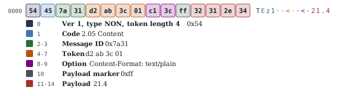
hex-dissect
A hex dump with each field’s bytes in its colour, and the fields decoded under them.
```hex-dissect title="A CoAP notification with the reading"
bytes: 54 45 7a 31 d2 ab 3c 01 c1 3c ff 32 31 2e 34
0 | Ver 1, type NON, token length 4 | 0x54 | navy
1 | Code | 2.05 Content | blue
2-3 | Message ID | 0x7a31 | green
4-7 | Token | d2 ab 3c 01 | amber
8-9 | Option | Content-Format: text/plain | purple
10 | Payload marker | 0xff | grey
11-14 | Payload | 21.4 | red
```
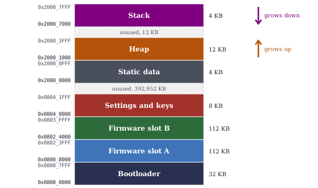
memory
An address map, highest address at the top, with gaps and the direction each region grows.
```memory
0x0800_0000 | 32 KB | Bootloader | navy
0x0800_8000 | 112 KB | Firmware slot A | blue
0x0802_4000 | 112 KB | Firmware slot B | green
0x0804_0000 | 8 KB | Settings and keys | red
0x2000_0000 | 4 KB | Static data | grey
0x2000_1000 | 12 KB | Heap | amber | up
0x2000_7000 | 4 KB | Stack | purple | down
```
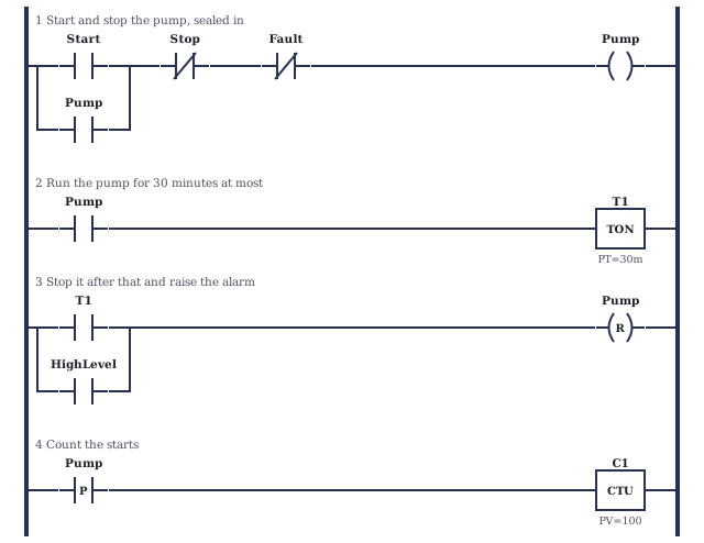
plc-ladder
Rungs of contacts, coils and boxes, with branches in parallel.
```plc-ladder
rung: Start and stop the pump, sealed in
NO Start | NC Stop | NC Fault | COIL Pump
branch: NO Pump
rung: Run the pump for 30 minutes at most
NO Pump | TON T1 PT=30m
rung: Stop it after that and raise the alarm
NO T1 | RESET Pump
branch: NO HighLevel
rung: Count the starts
P Pump | CTU C1 PV=100
```
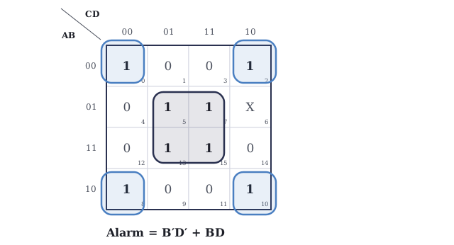
kmap
A Karnaugh map with a minimal cover looped on it, and the simplified expression.
```kmap name=Alarm
vars: A B C D
ones: 0 2 5 7 8 10 13 15
dont: 6
```
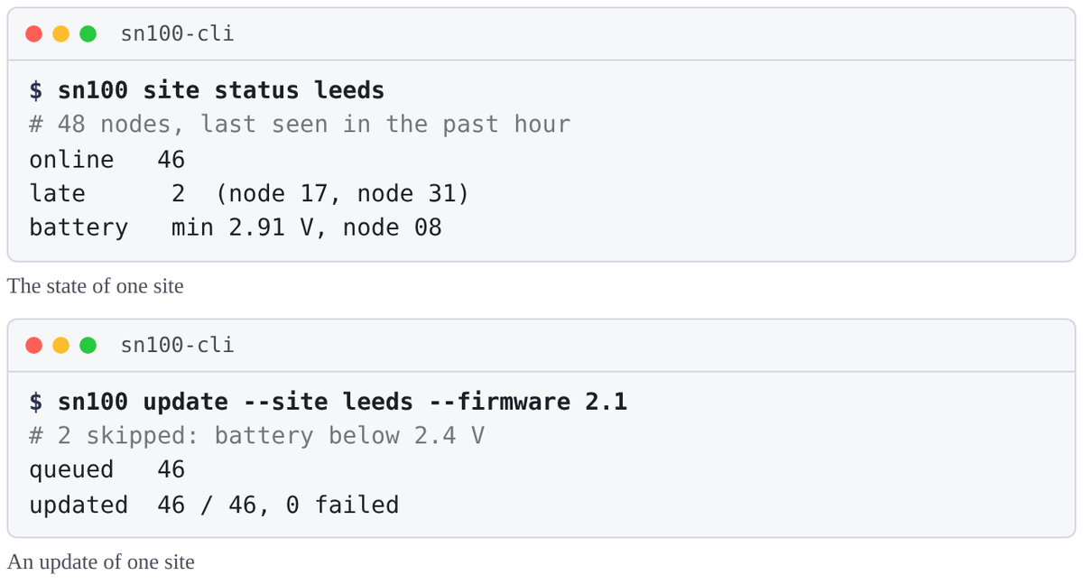
terminal
A terminal session: commands after a prompt, dimmed comments and output.
```terminal title="sn100-cli" cols=1
$ sn100 site status leeds
# 48 nodes, last seen in the past hour
online   46
late      2  (node 17, node 31)
battery   min 2.91 V, node 08
-- The state of one site

$ sn100 update --site leeds --firmware 2.1
# 2 skipped: battery below 2.4 V
queued   46
updated  46 / 46, 0 failed
-- An update of one site
```
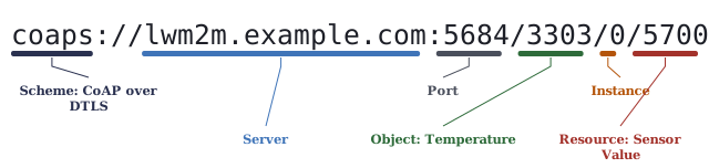
syntax-anatomy
A line of syntax with each part named.
```syntax-anatomy
coaps://lwm2m.example.com:5684/3303/0/5700
coaps | Scheme: CoAP over DTLS | navy
lwm2m.example.com | Server | blue
5684 | Port | grey
3303 | Object: Temperature | green
0 | Instance | amber
5700 | Resource: Sensor Value | red
```
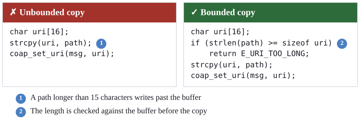
code-compare
Two versions of code side by side, with numbered notes.
```code-compare
@bad Unbounded copy
char uri[16];
strcpy(uri, path);          <1>
coap_set_uri(msg, uri);
@good Bounded copy
char uri[16];
if (strlen(path) >= sizeof uri)  <2>
    return E_URI_TOO_LONG;
strcpy(uri, path);
coap_set_uri(msg, uri);
-- 1 | A path longer than 15 characters writes past the buffer
-- 2 | The length is checked against the buffer before the copy
```